Airspeed
Description
See also: V-Speeds
Actual Airspeed Reference Line and Scale
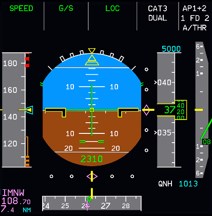
A white scale on a gray background moves in front of a fixed yellow reference line next to a yellow triangle to show airspeed. The minimum airspeed indication is 30 knots.
Speed trend
This is shown in yellow and starts at the speed symbol. It is an arrow that extends upwards or downwards from the speed symbol, depending on the trend of the aircraft's speed (whether accelerating or decelerating).
The tip shows the speed the aircraft will reach in 10 seconds if the rate of change remains constant. The pointer will only appear when it exceeds 2 knots and disappears when it is 1 knot.
It will also disappear if the FACs fail.
Target Airspeed
This is displayed in either magenta or blue depending on whether managed or selected speed is commanded. It is a triangle coming off from the right side of the speedtape. If the target airspeed is the FMGC computed airspeed, it will be displayed as a magenta triangle. If it is selected from the FCU by the pilots, it will be blue.
The target speed will be a magenta double bar when it is associated with the ECON speed range.
If the target speed is off the scale, the value is displayed as a number above or below the scale.
Mach Number
This is displayed in green and is shown if the Mach number reaches above 0.5. It is displayed underneath the scale.
Speed Protection
This is displayed in green and shows the speed at which overspeed protections become active.
This speed is VMO (maximum operating speed) + 6 knots or MMO (maximum Mach speed) + 0.01
ECON Speed Range
This appears in descent mode with ECON/AUTO SPD mode active. Two magenta half triangles will represent the upper and lower limits calculated by the FMGC. This replaces the target speed symbol.
The upper speed is equal to the target speed + 20 knots, limited to VMAX, VMO - 3 knots or MMO - 0.006, whichever is the lowest.
If a speed constraint or limit applies, then the upper margin is limited to ECON SPD + 5 kt.
The lower speed margin is the target speed - 20 knots. It is limited to green dot, F, S or VLS speeds, whichever is higher.
Minimum Selectable Speed (VLS)
The top of the amber strip along the speed scale represents this speed. It shows the lowest selectable speed and provides an appropriate margin to the stall speed. This information is inhibited from touchdown until 10 seconds after liftoff.
Alpha Protection Speed
The top of the black and amber striped strip along the speed scale represents this speed. It shows the speed corresponding to the angle of attack at which the alpha protections will become active. It is displayed when the aircraft is in normal pitch law.
Alpha Max Speed
The top of a red strip along the speed scale indicates this speed. It represents the speed corresponding to the maximum angle of attack that the aircraft can achieve in normal pitch law.
VMAX
The lower end of a red and black strip along the speed scale represents this speed. It is the lowest of:
- VMO or the corresponding to MMO
- VLE
- VFE
Stall Warning Speed (VSW)
The top of the red and black strip along the speed scale represents this speed. It is the speed at which the stall warning will occur. This information is inhibited from touchdown until 5 seconds after liftoff and is displayed only when operating in pitch alternate or pitch direct law.
V1
It is shown as blue numeral one (1) at a speed that the pilot inserted manually in the takeoff performance page in the MCDU. When it is off the scale, the upper part of the scale shows the speed in numbers. It disappears after liftoff.
Minimum Flap Retraction Speed (F)
This is displayed with a green letter F. It appears when the flap selector is in position 2 or 3.
Minimum Slat Retraction Speed (S)
This is displayed with a green letter S. It appears when the flap selector is in position 1.
VFE NEXT
It is displayed with an amber double bar (=) and shows the VFE corresponding to the next flap lever position. It appears when the aircraft altitude is below 15 000 feet or 20 000 feet depending upon the FAC standard.
VR (Rotation Velocity)
This is a blue dot on the right side of the speedtape. It displays the speed at which the aircraft can rotate.
V2
This is a magenta triangle on the right side of the speedtape. It displays the V2 speed which has been set in the TAKE OFF PERF page of the MCDU. V2 is the minimum speed that needs to be maintained in the event of an engine failure after V1 up to acceleration altitude.
V2+10 provides better climb performance (before acceleration altitude and during noise abatement program departures).
Engine Loss V2 Speeds
After takeoff, V2+10 is the targeted speed you should reach and maintain by the time you attain a height of 35 ft after takeoff until reaching the acceleration altitude.
When an engine failure occurs (shortly before or after takeoff), V2 is the minimum allowable speed. Pilots should aim to meet the criteria below at the point of engine loss:
- In a situation where the engine is lost before reaching V2 the targeted speed is V2.
- If the aircraft speed is higher than V2 then pilots should maintain the higher speed but not exceed V2+15.