Attitude and Guidance
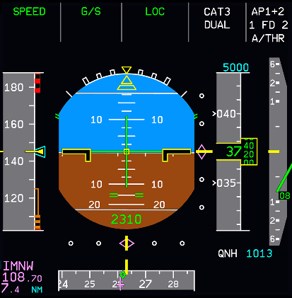
This is made up of several different parts that all come together to provide flight guidance to the pilots. It is an oval split in half with brown at the bottom and blue at the top. Blue indicates the sky and brown indicates the ground. The black line where they meet in the middle is the 0-degree attitude marker.
On top of the background are several markers and symbols that show the pilot several things, which are explained below.
Sidestick Order Indication
This is displayed as a white plus and is turned on when one engine is started. It indicates the total of the pilot's and first officer's sidestick orders.
Max Sidestick Deflection
It displays the corners of a square in white. It shows the pilots the maximum sidestick deflection (the maximum it can be moved). This is displayed when at least one engine is started.
Ground Roll Guidance Command
This is a green vertical bar displayed underneath the 0-degree line. It is displayed on the ground or below 30 feet radio altitude and if there is a localizer signal available. It shows the flight director yaw orders, to keep the aircraft on the runway center line.
Fixed Aircraft Symbol
This is displayed in black and outlined in yellow. The yellow outline is dimmed if the crew selects TRK-FPA, unless the FMA is in TO/GA or FLX mode. This symbol is fixed, and the background moves to display the bank angle and pitch of the aircraft.
Roll Scale
It extends off the top of the oval. The scale is in white and has markers at 0, 10, 20, 30 and 45 degrees of bank. If the bank angle exceeds 30, the aircraft will correct the bank angle back to 30 degrees once sidestick pressure has been released.
Roll Index
This triangle is underneath the roll scale, displayed in yellow, and shows the bank angle. When the bank angle exceeds 45 degrees, all the PFD symbols, except those for attitude, speed, heading, altitude and vertical speed disappear. The display returns to normal when the bank angle decreases below 40 degrees.
Pitch Scale
White markers that display the angle of pitch on the artificial horizon. There are markers every 10 degrees between 80 degrees nose up, and 80 degrees nose down, with a smaller marker every 2.5 degrees between 30 degrees nose up and 10 degrees nose down.
When the pitch angle exceeds 25 degrees nose up or 30 degrees nose down, all the PFD displays and indicators will become hidden.
Beyond 30 degrees, large red arrowheads indicate that attitude has become excessive and will show the direction to move the nose in order to reduce it. The display will return to normal once the pitch angle reaches lower than 22 degrees nose up or 10 degrees nose down.
Flight Control Protection Symbols
They are displayed in green on the sides of the artificial horizon:
- On the roll scale at ± 67 degrees to mark the bank angle limits.
- On the pitch scale at 15 degrees nose down or 30 degrees nose up to mark the pitch limits.
An amber X will replace these symbols if the protection is lost.
Sideslip Index
This is displayed in yellow underneath the roll index. It is a trapezoidal shape, and it moves underneath the roll index.
On the ground, it will display the lateral acceleration of the aircraft.
In flight, it will display sideslip. One centimeter (in the real aircraft) of displacement on the display indicates 0.2 g. The sideslip index will stop at 0.3 g.
If there is an engine failure at takeoff or go around, the sideslip index will change from yellow to blue.
Note that the sideslip target is blue if:
- Config 1, 2 or 3 is selected, and
- Any engine N1 is less than 80 %, and
- The difference between the engines' N1 exceeds 35 %
In this case, the sideslip index is called the beta target. When this index is centered with the roll index, the sideslip equals the sideslip target for optimum aircraft performance.
Flight Director
Two flight guidance modes are available, each having their own symbols.
Heading / Vertical Speed Reference
The PFD displays pitch and roll bars in green. They automatically move out of view at touchdown in rollout mode.
They flash for 10 seconds and then remain steady when:
- Reversion to the HDG V/S basic mode, or
- Change of selected flight level when alt capture mode is engaged, or
- Loss of LOC or G/S in land mode or the loss of land mode, or
- At the first autopilot or flight director engagement.
Track / Flight Path Angle
The inertial flight path vector defines the aircraft's horizontal and vertical track, taking wind effects into account. An associated flight path director guides the pilots onto the vertical and horizontal flight path targets.