Altitude Indicator
Description
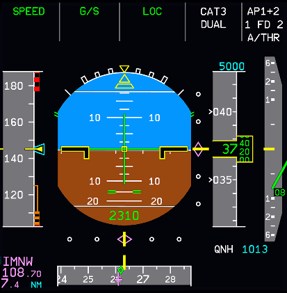
The altitude is displayed as a white moving scale and as a green digital readout on a gray background. NEG will appear on the background if the altitude is negative. The altitude window will change from yellow to amber if the aircraft has deviated from the FCU selected altitude.
If an MDA has been entered into the MCDU PERF page, the altitude numbers will change from green to amber once the aircraft goes below the chosen altitude.
Vertical Deviation
This green filled circle symbol appears next to the altitude corresponding to the theoretical vertical profile computed by the FMGC. It is displayed from the top of descent down to the MAP altitude. The flight crew can read the linear deviation directly from the altitude scale. The range is ± 500 ft. When the linear deviation value exceeds ±500 ft, the symbol stays at the range limit but changes to a half filled circle and the PROG page displays the exact value.
Target Altitude or Selected Flight Level Symbol
This is displayed in blue and shows the FCU selected altitude (if the QNH baro reference is selected) or the selected flight level (if STD baro reference is selected). If the FMGC is in vertical managed mode, the symbol will be magenta if it represents a constraint it will follow.
If the altitude is on the scale, the numbers will be displayed inside the symbol. If it is off the scale, the numbers will be displayed above or below the scale.
Target Altitude or Selected Flight Level (meters)
If metric alt is activated, this is shown in numbers above the altitude indicator. It is either magenta or blue depending on whether it's the FMGC calculated altitude or a pilot selected altitude.
Altitude Indicator (meters)
If metric alt is activated, this is shown under the barometric reference and is displayed in green numbers. It shows the altitude in meters.
Radio Height
This appears at the bottom of the artificial horizon and the aircraft is 2500 feet or lower (radio altitude)
If a decision height has been entered in the PERF page of the MCDU, then:
- The radio height appears in green when the decision height + 100 feet is less than the radio altitude and the radio altitude is less than 2500 feet.
- The radio height appears in amber when the decision height + 100 feet is greater than the radio altitude.
When the aircraft reaches the decision height, DH letters will flash in amber for 3 seconds and then stay in amber above the radio altitude indication.
If no decision height has been entered in the PERF page of the MCDU, then:
- The radio height appears in green when the radio height is greater than 400 feet but less than 2500 feet.
- In amber when the radio altitude is equal to or less than 400 feet.
The radio altitude changes every 10 feet down to 50 feet, then every 5 feet down to 10 feet, then every foot.
Landing Elevation
This is a horizontal bar on the scale that shows the landing elevation at the destination. It is displayed during flight phases 7 and 8 (800 feet radio altitude and touchdown) and if the QNH barometric reference mode is selected.
Ground Reference
A red ribbon alongside the scale displays the field elevation. It uses the radio altitude as the data source and is displayed below 570 feet. It moves up with the altitude scale as the aircraft descends. When the aircraft has touched down, the ribbon will be in the middle of the altitude window.