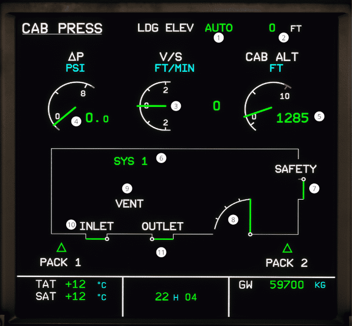
ECAM PRESS page
Back to ECAM System Display Overview
| Number | Name | Variation | Meaning |
|---|---|---|---|
| 1 | Landing elevation mode | LDG ELEV AUTO | The LDG ELEV is in AUTO. |
| LDG ELEV MAN | The LDG ELEV is not in AUTO. | ||
| Hidden | The MODE SEL is in MAN position. | ||
| 2 | Landing elevation | Green color | The landing elevation is set in the FMGS. |
| Hidden | The MODE SEL is in MAN position. | ||
| 3 | Cabin vertical speed | Green color | The cabin vertical speed is within normal operating range. |
| Amber color | The vertical speed is greater than 2000 ft/min. | ||
| Pulsion | The vertical speed is greater than 1800 ft/min, or hasn't reset yet (automatically resets at 1600 ft/min). | ||
| 4 | Cabin differential pressure | Green color | The cabin differential pressure is within normal operation range. |
| Amber color | The cabin differential pressure is smaller than 0.4 psi, or greater 8.5 psi. | ||
| Pulse | The cabin differential pressure is greater than 1.5 psi. | ||
| 5 | Cabin Altitude | Green color | The cabin altitude is within normal operations. |
| Red color | The cabin altitude is above 9550 ft. | ||
| Pulsion | The cabin altitude is at or above 8800 ft. | ||
| 6 | Active system indication | Green SYS 1 or 2 | The active system indication is active. |
| Amber SYS 1 or 2 | The active system is faulty. | ||
| Green MAN | The MODE SEL is in MAN. | ||
| 7 | Safety valve position | White SAFETY and green diagram | The safety valves are fully closed. |
| Amber SAFETY and amber diagram | One of the safety valve is partially closed. | ||
| 8 | Outflow valve position | Green diagram | The valve is within normal operations. |
| Amber diagram | The valve is open more than 95 % in flight. | ||
| 9 | VENT | White color | The ventilation is within normal operating range. |
| Amber color | The ventilation has one of the following faults: BLOWER FAULT, EXTRACT FAULT, or AVNCS SYS FAULT. | ||
| 10 | Inlet and extract indications | White color | The inlet and extract indications are within normal operating range. |
| Amber color | The inlet and extract indications has one of the following faults: BLOWER FAULT or EXTRACT FAULT | ||
| 11 | Inlet and Extract valve diagram | Green and connected | The inlet and extract valve is closed |
| Amber and connected | The inlet and extract valve position is not coordinated with the control position. | ||
| Green and disconnected at 90° | The inlet and extract valve is open | ||
| Amber and disconnected at 90° | The inlet and extract valve position is not coordinated with the control position. | ||
| Amber color and diagonal to the left | The inlet valve is in transit. | ||
| Amber color and diagonal to the right | The outlet valve is partially open. | ||
| Amber XX | The valve position is unavailable, or inconsistent data is received. |
